Page 1 of 1
Hard rev limiter on megajolt/e
Posted: Sat Feb 26, 2011 5:41 pm
by mini_mad69
Im having real trouble trying to get the hard limiter working on my megajolt/e.
I soldered in the board and got the car running, without trying to get the limiter working. I've been trying for the last couple of days, but im struggling to get it to work.
It's confusing to install the board into the unit as the guide is for the MJLJ v4, not the megajolt/e which is different.
Also im unsure where the wire goes from the unit itself, I understand it comes from the Pin on the plug, and goes to the centre pin of the coil pack.
But do I cut the existing wire from the coil pack? join onto it? Im unsure.
Could someone explain how to solder the board to the main board of the megajolt so I can check I've done this correctly, and then where the wire comes from the ECU to the coilpack?
CHeers in advance
Ben
EDIT: just to mention I understand the operation of it, the soft limiter is working well, but the car does push through it.
Posted: Sun Feb 27, 2011 12:33 am
by DannyP
Your original power feed that went to the coilpack needs to go to the limiter. Then the "out" from the limiter goes to the center(on a Ford style) pin of the coilpack.
Posted: Sun Feb 27, 2011 12:45 am
by mini_mad69
Ok, I did that and it didn't run.
So something is wrong in my wiring of the limiter board. Does anyone have a clear diagram or picture of how it's soldered to the main board?
Posted: Sun Feb 27, 2011 1:52 pm
by mini_mad69
Looking at the installation guide, it looks to me that the coil +12v that used to come from my fusebox and working fine, will now come from my megajolt unit unit.
So looking at this diagram.
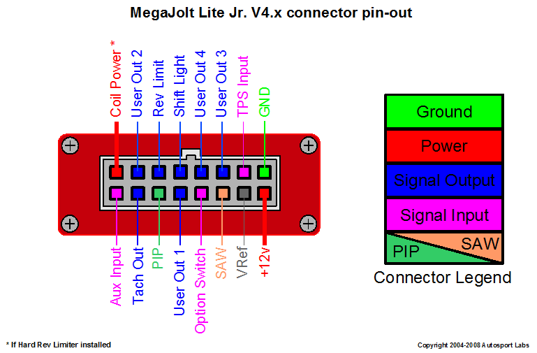
The top left pin (coil power) and the pin 2 spaces over to the right (rev limit) will both go to the centre pin of the coilpack, and the 12v I was using for the coilpack before will not be used?
Am I right?
Thanks
Posted: Sun Feb 27, 2011 6:27 pm
by brentp
Hi Ben,
While the board is a different revision, the 4 connections on the megajolt/e board remain the same. You essentially wire in the 4 PC Board pads on the Megajolt/E to the matching pads on the hard rev limiter, then slide the Rev Limiter board into the top slot of the Megajolt/E case.
these 4 wires are:
+12v pad on Megajolt/E to +12V pad on Hard rev limiter
COIL_POWER pad on Megajolt/E to COIL_POWER pad on Hard rev limiter
GND pad on Megajolt/E to GND pad on Hard rev limiter
Trigger pad on Megajolt/E to Trigger on Hard rev limiter
After this, you connect the the coil pack's center power lead to the the external COIL_POWER pin on the Megajolt connector.
How did you have it wired up before?
Posted: Tue Apr 12, 2011 9:18 am
by bobclevenger
Hi Brent,
So if we are using the latest boards we can just ignore the part of the posted instructions that say to cut a trace on the MJLJ board ?
Also, the instructions say to use #14 wire for the +12 VDC and the coil power connections, but the boards will only accept #18 wires; given the short runs if wired internally, is #18 sufficient?
Posted: Tue Apr 12, 2011 2:05 pm
by brentp
Which instruction are you referring to that has you 'cut a trace'?
Install the largest gauge wire you can- 14 might indeed be too big for the hole, but 16 or 18 will handle the coil current for that short distance, yes.
Posted: Tue Apr 12, 2011 5:21 pm
by bobclevenger
brentp wrote:Which instruction are you referring to that has you 'cut a trace'?
Install the largest gauge wire you can- 14 might indeed be too big for the hole, but 16 or 18 will handle the coil current for that short distance, yes.
From the "Hard Rev Limiter 1.2.0" page. The bottom of the page reads:
... Most ambitious: wire everything internally: Jumper GND connection to MJLJ GND;
Jumper +12V connection to MJLJ +12V (14 gauge wire);
Use a thicker gauge wire (14 gauge) for MJLJ +12V power, if necessary, as the +12v supply will supply current to the coil in addition to powering the MJLJ electronics;
Jumper trigger input to REV_LIMIT output on MJLJ board;
Cut the REV_LIMIT trace on the MJLJ board running from the ULN2003 to the REV_LIMIT connector pin. The REV_LIMIT pin will now be the new COIL power supply..
Connect the Rev limit COIL output to REV_LIMIT pin on MJLJ connector.
Emphasis added.
Posted: Thu Sep 01, 2011 10:45 pm
by trevil
I also found out that the howto is outdated, you dont cut anything on the newer versions. Just solder the wires.
Posted: Thu Sep 01, 2011 11:52 pm
by bobclevenger
Yeah, I tried it without cutting traces and it seems to work. I would have appreciated some feedback, though.
Posted: Fri Sep 02, 2011 4:05 am
by brentp
Thanks for the reminder. We'll update the docs with notes on the latest version.