
As broke4speed was trying to get his tacho to work after fitting a megajolt system I thought I would start a post on how to do a conversion.
This is at the experimental stage at the moment and hopefully we will be able to make the megajolt unit tach output work with cars original clocks.
I apologise in advance for the poor quality of the pictures. Crummy iPhone camera. I will try to improve them over time.
So first of all I disassembled the tacho to get to the tacho driver board (first 2 pictures). The tacho driver board (3rd picture) uses a SAK215 chip to control the rev counter, which is basically a current meter. After a bit of research I found the chip which is used http://www.datasheetarchive.com/SAK215-datasheet.html
I then drew out the circuit board into a circuit diagram to get an understanding of the circuitry, which is fairly similar to that in the datasheet.
Now the hack, I believe if we remove 2 components, namely a resistor and a capacitor and replace the resistor with a link wire, then we should be able to achieve what we wanted and hopefully drive the tacho just using the MJLJ.
VW Mk1 Golf Tacho Modification
Moderators: JeffC, rdoherty, stieg, brentp
-
NITROPIXIE
- Posts: 704
- Joined: Sun Sep 07, 2008 1:54 pm
- Location: Fareham, GB
VW Mk1 Golf Tacho Modification
- Attachments
-
- IMG_0546.jpg (17.78 KiB) Viewed 37132 times
-
- IMG_0545.jpg (17.96 KiB) Viewed 37132 times
-
- IMG_0544.jpg (20.3 KiB) Viewed 37132 times
1310 A-series Mini, lightened and built myself. V4 board and loving it
Rasputin22 - The Mini Forum
Rasputin22 - MK1 Golf Forum
Megajolt repair for the UK available
Rasputin22 - The Mini Forum
Rasputin22 - MK1 Golf Forum
Megajolt repair for the UK available
-
NITROPIXIE
- Posts: 704
- Joined: Sun Sep 07, 2008 1:54 pm
- Location: Fareham, GB
So here is the hack,
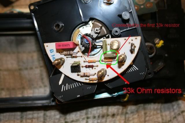
The red circled component (resistor) is to be replaced with a link. The green circled component (capacitor) is removed. Hopefully this will now make the tacho work with the MJLJ tacho out.
The resistor is a 33K Ohm resistor and there are 2 of them before the signal reaches the chip. This hack may require the second resistor to be reduced in size (not to be removed).
It should also be noted that no damage would happen to the circuit board or MJLJ using the MJLJ tacho out to provide and output signal using this hack.
On another note I have found out that by changing other components around the board we could actually redesign the circuit board so the tacho could be used on other cylinder engines, such as a 6 cylinder, etc.
So fingers crossed we will have a working tacho
- Attachments
-
- IMG_0546 modified.jpg (24.4 KiB) Viewed 37130 times
1310 A-series Mini, lightened and built myself. V4 board and loving it
Rasputin22 - The Mini Forum
Rasputin22 - MK1 Golf Forum
Megajolt repair for the UK available
Rasputin22 - The Mini Forum
Rasputin22 - MK1 Golf Forum
Megajolt repair for the UK available
-
Broke4speed
- Posts: 100
- Joined: Mon Mar 30, 2009 4:49 pm
I'll be digging out my spare cluster! 
Thanks Mr.PIXIE! I should have an update shortly.
For non-electrical-luddite clarification: use a jumper/link where the resistor goes, and remove the capacitor completely? Does a link need to go there as well? I'm presuming by 'link', a small piece of wire or a leg from a spare resistor would do?
Thanks Mr.PIXIE! I should have an update shortly.
For non-electrical-luddite clarification: use a jumper/link where the resistor goes, and remove the capacitor completely? Does a link need to go there as well? I'm presuming by 'link', a small piece of wire or a leg from a spare resistor would do?
-
Broke4speed
- Posts: 100
- Joined: Mon Mar 30, 2009 4:49 pm
Of course they made it different for the NA market, sigh. The chip is the same, but the board is different. The components appear similar, but not enough for me to just start chopping  . Any ideas?
{edit} In the pic with the circled components, the layout is like this: ground point/standoff to the printed circuit board-->33k Ohm resistor-->one leg of a green thing-->second 33k Ohm resistor.
Probably not much help, lol. I'll see if I can find a better way of describing it.
{edit} In the pic with the circled components, the layout is like this: ground point/standoff to the printed circuit board-->33k Ohm resistor-->one leg of a green thing-->second 33k Ohm resistor.
Probably not much help, lol. I'll see if I can find a better way of describing it.
-
Broke4speed
- Posts: 100
- Joined: Mon Mar 30, 2009 4:49 pm
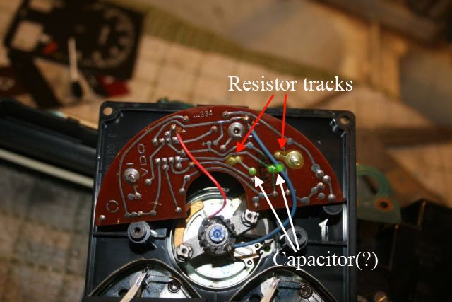
Ok, the yellow 'dots' are the resistor track, notably the one that connects to the standoff and then to the capacitor. The green 'dots' are what I assume is the capacitor.
To do this mod, I'm guessing that I'd desolder the capacitor, but make sure the tracks it taps into are still solid, so the circuit is still complete. The same goes for adding the resistor replacement jumper, to make sure it still connects to the second resistor in the line.
To do this mod, I'm guessing that I'd desolder the capacitor, but make sure the tracks it taps into are still solid, so the circuit is still complete. The same goes for adding the resistor replacement jumper, to make sure it still connects to the second resistor in the line.
-
NITROPIXIE
- Posts: 704
- Joined: Sun Sep 07, 2008 1:54 pm
- Location: Fareham, GB
That's the conclusion I have come to also broke4speed. Remove the resistor and replace with a wire link and also remove the capacitor. Keep all the tracks as they were and try not to damage them. If they become damaged then you can use solder to remake the track.
Ryan
Ryan
1310 A-series Mini, lightened and built myself. V4 board and loving it
Rasputin22 - The Mini Forum
Rasputin22 - MK1 Golf Forum
Megajolt repair for the UK available
Rasputin22 - The Mini Forum
Rasputin22 - MK1 Golf Forum
Megajolt repair for the UK available
-
Broke4speed
- Posts: 100
- Joined: Mon Mar 30, 2009 4:49 pm
-
Broke4speed
- Posts: 100
- Joined: Mon Mar 30, 2009 4:49 pm
There's one other thing...
Since my original tach picked up off the positive of the coil (IIRC), it is constantly fed a 12v signal. When I pull the tach wire off the coil, the car dies. Since the MJLJ went in, I've just had this connected to a +12v source. The fuel pump relay is connected to this wire for it's 12v, and I'm cleverly using the stock relay location for my carb pump ( ). I'm just going to run the signal right to the cluster at the connector, since I'm a bit reluctant to track back through my harness in -10*C. As it stands, the tach mod might have to wait for installation . I really don't want to shatter any of the brittle dash trim, it's tough to find replacements. I'll see if I can ghetto something up though .
Since my original tach picked up off the positive of the coil (IIRC), it is constantly fed a 12v signal. When I pull the tach wire off the coil, the car dies. Since the MJLJ went in, I've just had this connected to a +12v source. The fuel pump relay is connected to this wire for it's 12v, and I'm cleverly using the stock relay location for my carb pump (
-
Broke4speed
- Posts: 100
- Joined: Mon Mar 30, 2009 4:49 pm
Mod went super easy, I'm getting the hang of this soldering thing, lol. I'd be lost without my vacuum tool though.
Used the long end of a resistor as the jumper, and removed the capacitor completely. The printed circuitboard is pretty rough, but continuity is still there between the tach standoff and the connector, so it should be good to go.
Hopefully we'll get a mild day soon and I can give it a shot. I've got to add the tach-out wire to my MJLJ first though, doh.
-
NITROPIXIE
- Posts: 704
- Joined: Sun Sep 07, 2008 1:54 pm
- Location: Fareham, GB
There are 2 main types of electronic tachometers which I know of, RVI and RVC.Broke4speed wrote:There's one other thing...
Since my original tach picked up off the positive of the coil (IIRC), it is constantly fed a 12v signal. When I pull the tach wire off the coil, the car dies. Since the MJLJ went in, I've just had this connected to a +12v source. The fuel pump relay is connected to this wire for it's 12v, and I'm cleverly using the stock relay location for my carb pump (
RVI are an older design and are current sensing. To sense the current the tacho is placed in line with the power lead to the ignition coil. These tacho's tend have 2 electronic connectors, one from the ignition switch and the other to the coil. This is what you have described, I believe you could use this type of tacho with a coil pack as it still only uses +12v, not sure if there would be any adverse effects though such as reduced power to the coil pack but the ignition events number the same.
RVC senses the voltage and does this with a square wave input (0-12v) from the points or electronic distribution unit, which equates to the negative side of the ignition coil. These tacho's tend to have 3 connectors, one ground, one ignition switched positive (to provide power to the tacho circuitry) and finally one to the negative side of the coil for signal input.
1310 A-series Mini, lightened and built myself. V4 board and loving it
Rasputin22 - The Mini Forum
Rasputin22 - MK1 Golf Forum
Megajolt repair for the UK available
Rasputin22 - The Mini Forum
Rasputin22 - MK1 Golf Forum
Megajolt repair for the UK available
-
Broke4speed
- Posts: 100
- Joined: Mon Mar 30, 2009 4:49 pm
It's fairly mild here today, I might give the modded tach (and stock) a try. I'll leave the current wiring the way it is and run the tach signal to the cluster, vs. using the stock in-bay wire. This will take the whole 'car no starty' thing out of the picture, lol. I'm positive I could track that back and wire it up differently, leaving access to the stock tach wire in the bay...but, it's still not THAT warm in the garage 
-
Broke4speed
- Posts: 100
- Joined: Mon Mar 30, 2009 4:49 pm
It WORKS!
...well, actually, I tested the stock unmodded tach as well, and it also works with the MJLJr tach-out, lol. The modded one responds a bit faster though, although both seem to be out ~300 rpm at idle, and ~100-200 at 3000 rpm. I'm thinking it's not the most accurate tach to begin with, since the stocker is out exactly the same amount as the modded one. I don't have a stock car to test with, but without a digital RPM gauge/timing light, there's no real way of telling anyway.
The NITROPIXIE-mod definitely has a faster response rate than the unmodded one, so it's definitely worth it IMO.
Thanks Ryan!
-
NITROPIXIE
- Posts: 704
- Joined: Sun Sep 07, 2008 1:54 pm
- Location: Fareham, GB
That's brill news, well done
The reason for the tacho not being exact is the tolerance of the components (resistors, etc) used as the circuit boards were massed produced and i'm guessing not calibrated with too much precision.
Also a possible reason why there is increased accuracy with higher rpm's is that the alternator is kicking out more power/voltage and so it has an effect on this tacho circuit as there is no semi conductor voltage regulator like you see in modern circuit boards.
If you wanted, more modifications could be made to stabilise the tacho circuitry better for improved accuracy. But isn't necessary unless you wanted.
1310 A-series Mini, lightened and built myself. V4 board and loving it
Rasputin22 - The Mini Forum
Rasputin22 - MK1 Golf Forum
Megajolt repair for the UK available
Rasputin22 - The Mini Forum
Rasputin22 - MK1 Golf Forum
Megajolt repair for the UK available
-
Broke4speed
- Posts: 100
- Joined: Mon Mar 30, 2009 4:49 pm
-
NITROPIXIE
- Posts: 704
- Joined: Sun Sep 07, 2008 1:54 pm
- Location: Fareham, GB
Ha ha, don't worry about it. Glad to helpBroke4speed wrote:
Thanks again for the help, I owe you a beverage of choice, although postage might be difficult
1310 A-series Mini, lightened and built myself. V4 board and loving it
Rasputin22 - The Mini Forum
Rasputin22 - MK1 Golf Forum
Megajolt repair for the UK available
Rasputin22 - The Mini Forum
Rasputin22 - MK1 Golf Forum
Megajolt repair for the UK available