
Looking for some info on the signals I should see at the coil output...a and b.. at cranking.. is it a Neg pulse to fire the coils?
I know this is a dumb question, but My install was up and running great,, about 20hrs,, and then it quit firing on 2 cly. ( one side of the coil ) and rather than remove the coil.. un hot-glue the connector I made for the coil, and risk High voltage shock,,,
I would much rather test the edis module first....LOL
Also ,, does anyone know where to get the 4cly coil power plug?
tests for the 4-edis module
Moderators: JeffC, rdoherty, stieg, brentp
well what is the EDIS voltage or signal at the pin numbers 10 & 12?
is it a 12v+ that stays at 12v+ until it goes Neg and fires the coil.. or is it a 5v+ that rises to 12v+ and fires the coil.. or a open circuit until the EDIS closes and connects it to ground ( like a switch )?
I understand how a coil works,,, I need to know how the EDIS fires the coil.. different controllers fire coils in different ways.. MDS .. CDS... Threshold waveform,,,ect
I'm trying to test my EDIS and want to know what I should see as a output at Pins 10 & 12...
Thanks for your reply
bmc,
I don't have a wire hooked up to pin #2 on the EDIS...
And if your speaking of the coil, pin #2 is 12v+ pin1 is 1&4cly coil.. and pin3 is 2&3cly coil..
I have a bare minimum install like this: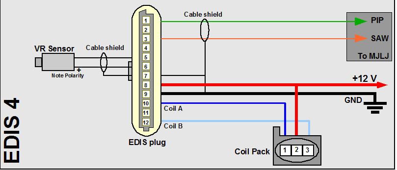
what I need to know is what kind if signal should I have at pins 10 &12 of my EDIS4 when my motor is turning over.
I haven't looked at the coil drivers of my EDIS8. As I understand it the EDIS sinks the coil to ground (or close to it) while charging the coil and then opens to fire the coil. Somewhere online I've seen a scope trace that showed what you're looking for, each coil (-) ramped up until the coil saturated and then a quick drop. I don't remember the amplitude or pulse width anymore. Never had to concern myself with it. So back to my previous question, have you simply compared pin 10 to pin 12? 90% of the time with these the coil ends up being the problem.