Power Led?

Megajolt Kit assembly Question and Answers. Be sure to review the <a href="http://www.autosportlabs.net/MJLJ_V4_kit_assembly_guide">Kit assembly guide</a>

Moderators: JeffC, rdoherty, stieg, brentp

Post Reply
dr.occa
Posts: 243
Joined: Fri Feb 23, 2007 10:52 pm
Location: TX

Power Led?

Post by dr.occa »

I'm not sure if this question was already asked (BrentP referenced it somewhere in a Shift Light discussion) but what would be the safest way to wire in an led to indicate that the MJLJ is on?

brentp
Site Admin
Posts: 6275
Joined: Wed Jan 24, 2007 6:36 am

Post by brentp »

You can wire in an LED powered by the 5V output side of the voltage regulator- it's the pin on the voltage regulator that connects to the positive side of C2.

A 470 ohm resistor in-line should be enough current limiting.

Regards,
Brent Picasso
CEO and Founder, Autosport Labs
Facebook | Twitter

dr.occa
Posts: 243
Joined: Fri Feb 23, 2007 10:52 pm
Location: TX

Post by dr.occa »

brentp wrote:You can wire in an LED powered by the 5V output side of the voltage regulator- it's the pin on the voltage regulator that connects to the positive side of C2.

A 470 ohm resistor in-line should be enough current limiting.

Regards,
much obliged brentp! please bear with me; would it be 5V output>470 ohm res>led(- or +?)>+ side of C2???

a lot of you guys on here know way too much about this stuff!!! i'm trying to keep up.

MartinM
Posts: 433
Joined: Sat Aug 27, 2005 12:08 pm

Post by MartinM »

The 5V output that goes to C2 > 470 ohm res > led+ (the longer lead or the rounded side of the case)

led- (the shorter lead or the flat side of the case) > ground

dr.occa
Posts: 243
Joined: Fri Feb 23, 2007 10:52 pm
Location: TX

Post by dr.occa »

aside from the problems i'm having, thanks for the feedback and help brentp & MartinM!

some pics w/ the new bright white led:

Image

Image

Ken555
Posts: 92
Joined: Fri Sep 07, 2007 8:24 pm
Location: Aberdeenshire
Contact:

1 step further

Post by Ken555 »

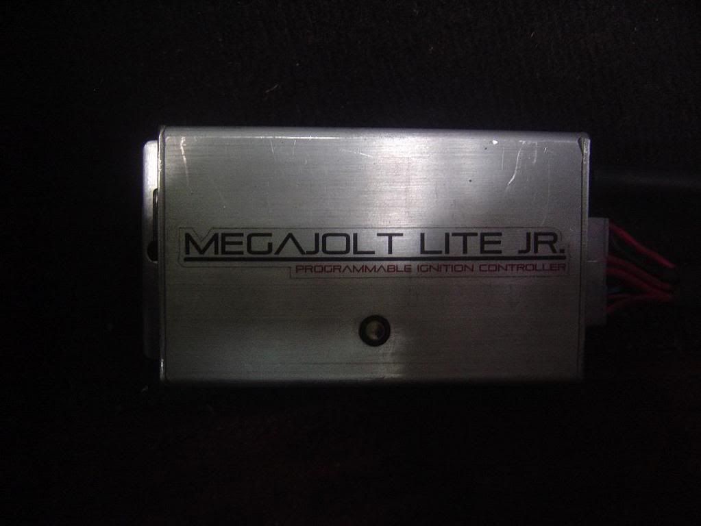
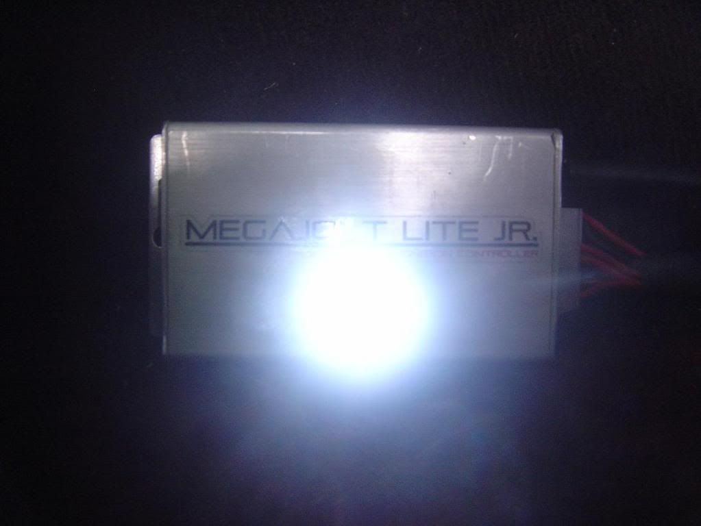
In my planned installation I can reach the ECU, so I fitted the box with a switch
and bi-colour LED to indicate the map in use.

Image Image

A Tri-Colour led, fed thru the same DPDT switch that does the switching.
Last edited by Ken555 on Sun Mar 16, 2008 12:39 am, edited 1 time in total.

DannyP
Posts: 417
Joined: Sun Apr 09, 2006 3:48 pm

Post by DannyP »

That's an excellent idea, Ken, I'll be mounting mine in a similar accesible location.

Ken555
Posts: 92
Joined: Fri Sep 07, 2007 8:24 pm
Location: Aberdeenshire
Contact:

Post by Ken555 »

Image

A bad diagram of how I wired it. The diode is a 3 lead, common anode one. In the UK, Maplin code CJ53H

Powered by the 5V output side of the voltage regulator.

I have a V2 board, so would need changed for a V3.

dr.occa
Posts: 243
Joined: Fri Feb 23, 2007 10:52 pm
Location: TX

Post by dr.occa »

well executed Ken!

luke6040
Posts: 113
Joined: Wed Dec 05, 2007 12:48 am
Contact:

Post by luke6040 »

i kno this an old thread but i want to add a power on led and was just wondering where is best to ground it out?
has anyone got some pics or a diagram maybe, i dond wanna get it wrong lol.

Post Reply