Testing MJLJ --> MINI A-Series 1360cc

Show off your Megajolt installations, vehicles and action shots here!

Moderators: JeffC, rdoherty, stieg, brentp

Salamander
Posts: 89
Joined: Mon Nov 13, 2006 9:46 pm

Testing MJLJ --> MINI A-Series 1360cc

Post by Salamander »

Hola desde chile,

Esperé mucho tiempo para que llegara mi MJLJ de U.S.A. y una vez que lo tube en mis manos lo armé y probé de la forma mas artesanal.
Estaba preocupado porque no sabía como hacer la conexión entre el MJLJ y el PC, al final era tan fácil como comprar un cable NULL MODEM just... plug&play :lol:

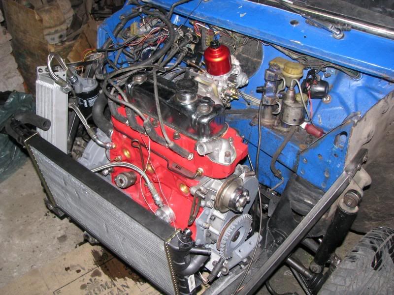
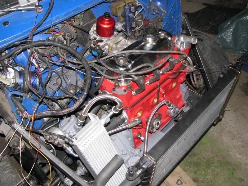
Les muestro fotos de pruebas.

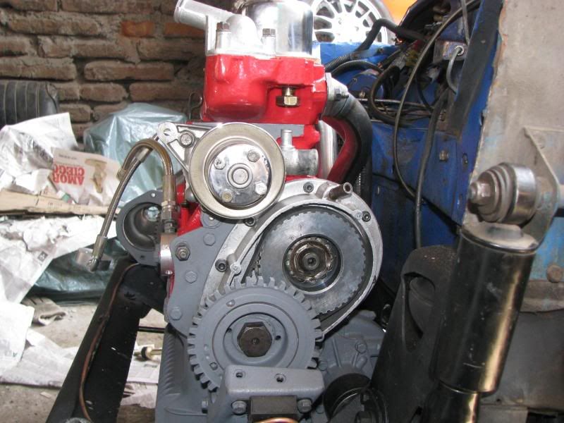
La señal de la polea dentada la hice girar con el taladro de pedestal y funcionó de las mil maravillas.
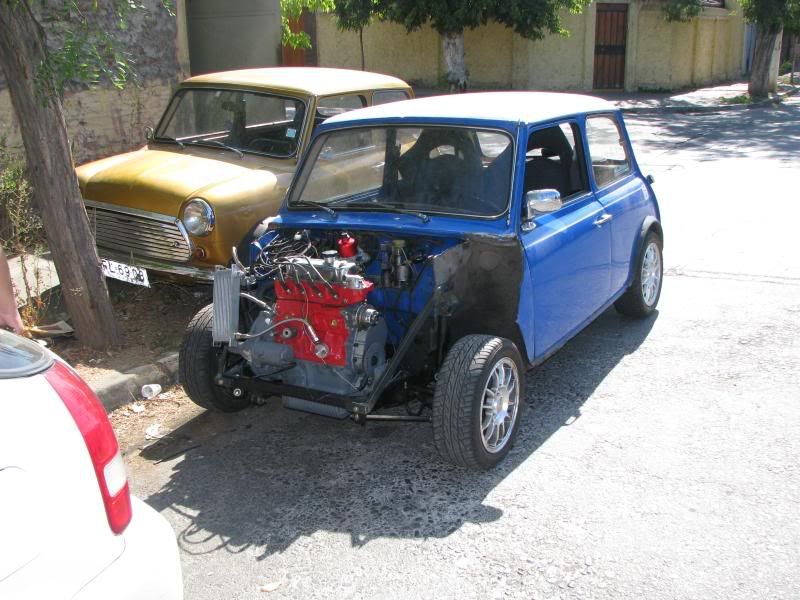
Una vez que tenga montado el sistema en mi vehículo, les mostraré en detalle el trabajo.

Image
Image
Image
Image
Image
Image
Image
Image
Image
Last edited by Salamander on Tue Nov 23, 2010 2:47 pm, edited 1 time in total.

Salamander
Posts: 89
Joined: Mon Nov 13, 2006 9:46 pm

Post by Salamander »

es posible hacer esto pero con 4 cilindros - bobinas independientes y eliminar el coil pack?

Ken555
Posts: 92
Joined: Fri Sep 07, 2007 8:24 pm
Location: Aberdeenshire
Contact:

Post by Ken555 »

Rough translation of posts.

1.
Hello from Chile,

I waited for long time so that my MJLJ arrived from U.S.A. and once tube in my hands I armed it and I proved of the artisan form but.
It was worried because it did not know like making the connection between the MJLJ and the PC, in the end was as easy as to buy a cable NULL MODEM just... plug&play

I show photos to them of tests.

The signal of the dentated pulley I rotated it with the pedestal drill and worked of the thousand wonders.
Once it has mounted the system in my vehicle, I will show in detail the work to them.


2.
it is possible to do this but with 4 cylinders - independent coils and to eliminate the coil pack?

Salamander
Posts: 89
Joined: Mon Nov 13, 2006 9:46 pm

Post by Salamander »

Thanks ken555, I do not speak very good English.

Thanks for your help to translate the text.
1 - I need to know how to connect or using the REV LIMIT, In Chile no electronic components to be able to do.

2-Configurable Outputs: output 1, output 2, output 3 and outputv 4, which use voltage? The diagram shows 0.3A negative, but how much is the voltage? , It is possible to put a relay and use a fuel injection additional according to the rpm's that I want? .
Thank you.

Ken555
Posts: 92
Joined: Fri Sep 07, 2007 8:24 pm
Location: Aberdeenshire
Contact:

Post by Ken555 »

apesadumbrado sobre el español pobre ;)


1.Si usted no tiene ningún componente, hasta que usted puede comprar un kit, usted puede utilizar el alambre del corte de la revolución para desconectar la energía a la bobina. Esto trabajará pues un límite de la revolución.

2.Las salidas producen una tierra o la tierra (0v) y pueden hacer frente a 12V 0.5Amp

intente esto también
http://babelfish.altavista.com/babelfis ... FMain_Page

Salamander
Posts: 89
Joined: Mon Nov 13, 2006 9:46 pm

Post by Salamander »

Ken555 wrote:apesadumbrado sobre el español pobre ;)


1.Si usted no tiene ningún componente, hasta que usted puede comprar un kit, usted puede utilizar el alambre del corte de la revolución para desconectar la energía a la bobina. Esto trabajará pues un límite de la revolución.

2.Las salidas producen una tierra o la tierra (0v) y pueden hacer frente a 12V 0.5Amp

intente esto también
http://babelfish.altavista.com/babelfis ... FMain_Page
Thanks, I will try.
The link is broken? Not working

Salamander
Posts: 89
Joined: Mon Nov 13, 2006 9:46 pm

Post by Salamander »

Here I show them photos of the work of the engine with my MINI 1380 & Swiftune 5.
I am still working on the engine, missing details. The engine runs smoothly, first install the MJLJ an engine 850 to make test, then settles at the MIGLIA.

Image
Image
Image
Image
Last edited by Salamander on Fri Apr 18, 2008 2:37 pm, edited 1 time in total.

KLAS
Posts: 93
Joined: Thu Oct 20, 2005 4:01 pm
Location: Germany

Post by KLAS »

very nice job relocating the oil filter

Salamander
Posts: 89
Joined: Mon Nov 13, 2006 9:46 pm

Post by Salamander »

Hi, I have a question:

The MJLJ works well, I have no problems yesterday as disarmament to connect the switch option (2 map), and install an ignition led.

Reviewing electronic components, I found a capacitor almost burnt (C14), it is normal? :oops:

Image
Image
Image

Salamander
Posts: 89
Joined: Mon Nov 13, 2006 9:46 pm

Post by Salamander »

here is the short video for the first start

http://es.tinypic.com/player.php?v=2hpio9z&s=3

Salamander
Posts: 89
Joined: Mon Nov 13, 2006 9:46 pm

Post by Salamander »

No one responded to my question :cry:

david jenkins
Posts: 204
Joined: Tue Feb 14, 2006 2:14 pm
Contact:

Post by david jenkins »

Regarding C14 - things to think about are:

Was it soldered in the correct way round?

Was it the correct voltage rating? (if it's from a kit, it was probably OK)

Did it get overheated when you soldered it into place?

brentp
Site Admin
Posts: 6275
Joined: Wed Jan 24, 2007 6:36 am

Post by brentp »

Apologies for not noticing your question- I would've seen it sooner if it was posted in the main help-related forums.

David is correct- you will want to first check for proper polarity. The capacitor is rated at 10V, it should be fine at the 5V levels seen in the TPS VRef circuit.

Regards,
Brent Picasso
CEO and Founder, Autosport Labs
Facebook | Twitter

TwoSheds
Posts: 64
Joined: Sat Jan 12, 2008 9:44 am
Location: UK, near Leeds

Post by TwoSheds »

david jenkins wrote: Did it get overheated when you soldered it into place?
I also wondered about this. Now I am no expert so please feel free to ignore/ridicule me for this comment, but it looks to me (from D4 in particular) like perhaps the solder was applied from the component side of the board which, as I understand it, is the wrong side and will result in more heat going into the components.

TwoSheds

brentp
Site Admin
Posts: 6275
Joined: Wed Jan 24, 2007 6:36 am

Post by brentp »

From how it looks discolored near the tip, I believe the capacitor was not damaged due to excessive soldering heat. Mr. Salamander can comment whether he felt too much heat was applied during construction...

I think with the diode, a little bit extra solder was applied and it flowed from the bottom, creating the blob.
Brent Picasso
CEO and Founder, Autosport Labs
Facebook | Twitter

Post Reply