Ok,just been assembling the MB,and have tested the C7 and C5. Here are pictures how I am doing it. I'm sure someone will spot my error.
I am using a 9volt battery
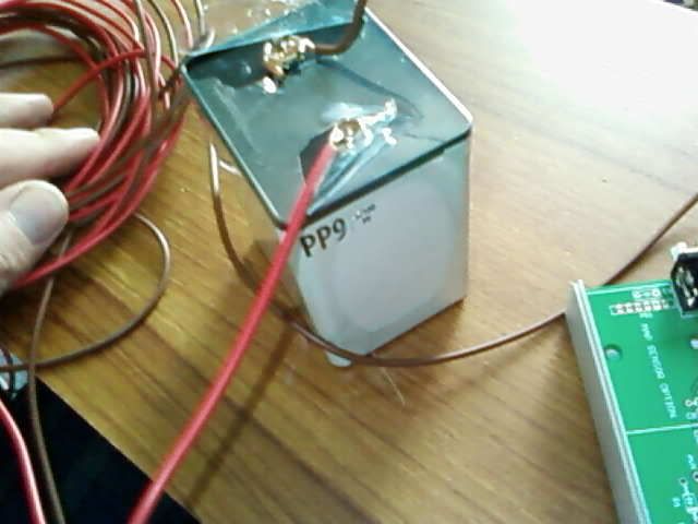
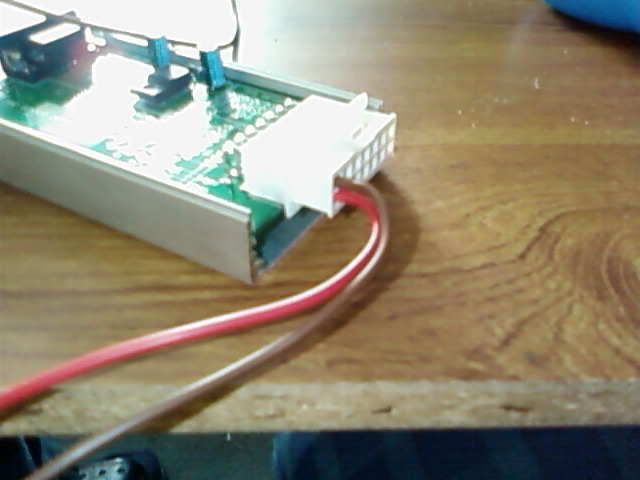
and I have connected just GND and Live wires to the molex to power up
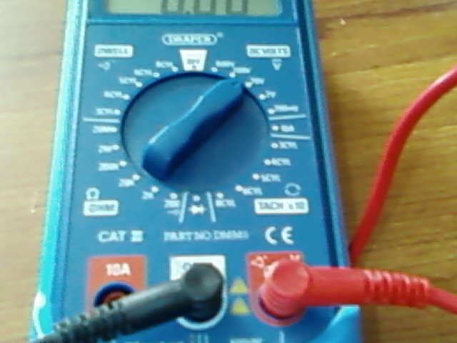
and here is my multimeter
thanks in advance
no 5volt
Moderators: JeffC, rdoherty, stieg, brentp
Thanks for your reply Danny
didn't know what cold solder is,I suspect it means not enough heat.
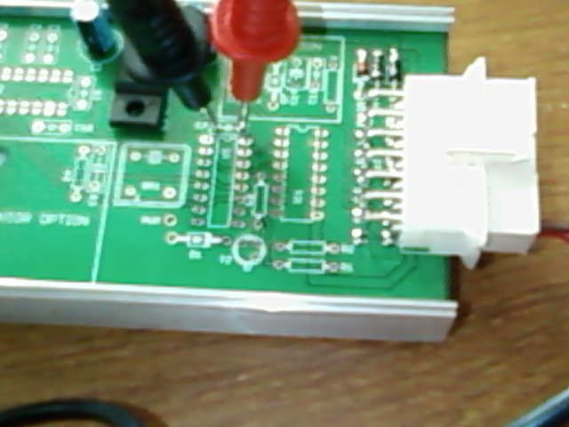
I don't know if you can see the picture clearly,my mobile camera isn't greatDannyP wrote:Post a picture of how the components are installed.
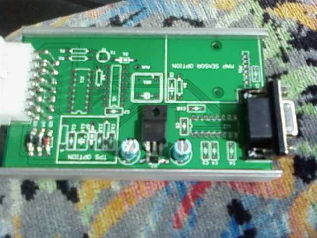
doesn't seem so,but I am comparing my build against Brents photosDannyP wrote: Possibly a reversed diode?
Oh yeh,C10,that is what I meant,honestDannyP wrote:Also, you must check at C7 and C10, not C5.
DannyP wrote:Check all your solder joints, possibly a cold solder?
didn't know what cold solder is,I suspect it means not enough heat.
Yep - the diagram is looking into the board, so it's the same as looking into the back of the plug....
...so with the (EDIT) notch at the top and everything horizontal, the power connections are on the right. Yours are on the left...
EDIT: If the next question is "how do I get the pins out of the Molex?" then:
a) use a proper pin removal tool
b) use a proper pin removal tool
c) use a proper pin removal tool
d) if you soldered the wires to the pins, you could pull very hard on the wires. You will eventually pull the pin out. You might be lucky and not damage the inside of the plug, or you might damage it. If you do, you won't get a new pin to locate securely. If you never want to use PGM2 or TACH OUT ever then that's OK, otherwise you will need a new plug. You also will damage the pin, and have to use a new one
e) don't bother - accept that you PGM2 wire is brown and your TACH OUT wire is red.
If I couldn't do a) to c), I'd do e)
You are correct Martin,thanks m8!
Just to justify me being a muppet,on the diagram the notch replicates the plug characteristics. The molex connected to the PCB has an alcove.
Anyway,the molex plug that the wires are connected to,is numbered 1)GND 8)12v
had a fiddle with the pins,and tugged at the wires,sod it I thought I'll just have to solder green wire onto brown,and whatever colour PGM3 will be.MartinM wrote:e) don't bother - accept that you PGM2 wire is brown and your TACH OUT wire is red.
If I couldn't do a) to c), I'd do e)
Just to justify me being a muppet,on the diagram the notch replicates the plug characteristics. The molex connected to the PCB has an alcove.
Anyway,the molex plug that the wires are connected to,is numbered 1)GND 8)12v
Even though it states the orientation in the diagram, it's proven it's been a source of confusion more than a few times. I think it would help to clarify the graphic a bit more, perhaps showing the actual end view of the board.
I noticed, connecting power on the opposite pins of the plug seems to have no detrimental effect. However, I can't claim I designed it this way intentionally!!