1835cc with dual 40mm Kadrons
I went from this....

to this....

and finally to this Pulley version 2.0 - this is what I wanted to do from the beginning. Drilled the triggers into an equalizer pulley.


Once I removed the fuel pump and distributor I needed to cover the holes with something else. Most VW shops sell a fuel pump block off. As for the distributor hole – I opted to cut the top of an old distributor and use the stock clamp to hold it in place. I had a friend paint an eyeball on the remaining distributor shaft with the hope of being able to see when I had #1 cylinder lined up (for adjusting valves). The pupil of the eye spins when the motor is running.
Performance has been outstanding. I can honestly say that my engine is running smoother than ever. Throttle response is great, idle is solid, and it drives like a new car. Fuel economy needs some work, but that may be due to my heavy foot and the fact that it runs a little rich.

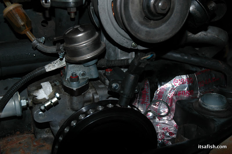
This shows the VR sensor on the one of the original mounting brackets. I ended up buying 3 inch 90 degree brackets from Home Depot to hold the sensor.

I trimmed the mounting holes off the VR sensor and opted to clamp it to the bracket instead. The copper piece is half of a grounding clamp.

Locating the coil pack is a challenge. The clearance behind a doghouse fan shroud is about 4 inches. The coil pack with wires attached is a quarter inch shy of 4 inches.

Side view of the mounting bracket. Note the clearance between the fan belt.

Another view of the mounting bracket.

Early attempt to mount trigger wheel to pulley. Note the addition holes from mistakes made.

One thing I did discover is that the trigger wheel needs to be offset from the pulley in order for the VR sensor to get a clean signal.

This shows the trigger wheel with the serpentine belt pulley (after I cut the belt part off) being used to align the trigger wheel to the pulley. The center piece can be pressed out afterwards.

This shows the coil pack and EDIS module (lower right) on the test engine. I started the engine on the stand to verify the system worked.