
hello all,
I just got a tach adapter for use on my zetec capri, I have a aftermarket rev counter what needs a a signal from the neg side of the coil. Because I am using the zetec red ESC box with the vac take off I am not running a MJ as yet but still need of a rev counter I have tried many way all with no result the best I can get is the rev counter to read half the RPM, so I invested in the tach adapter to solve my problems but with it wired up as the web site says I get noting on the rev counter, but if I take off one of the coils it goes back to reading half. So what else do I need to do to get this to work?
Tach Adaptor not working
Moderators: JeffC, rdoherty, stieg, brentp
Hello,
Tachometers vary quite a bit in what they need for a signal, and can be tough to get right in some cases.
We designed our tach adapter to follow the widely known diode isolation circuit plus the addition of 100K bypass resistors as some tachs seem to need to see a small constant 12v signal between ignition pulses; the older Porsche 914 tach we are using in our race car is one example.. So, it should work with the vast majority of tachometers out there.
Schematics here:
http://www.autosportlabs.net/images/4/4 ... er_sch.png
What you can try doing:
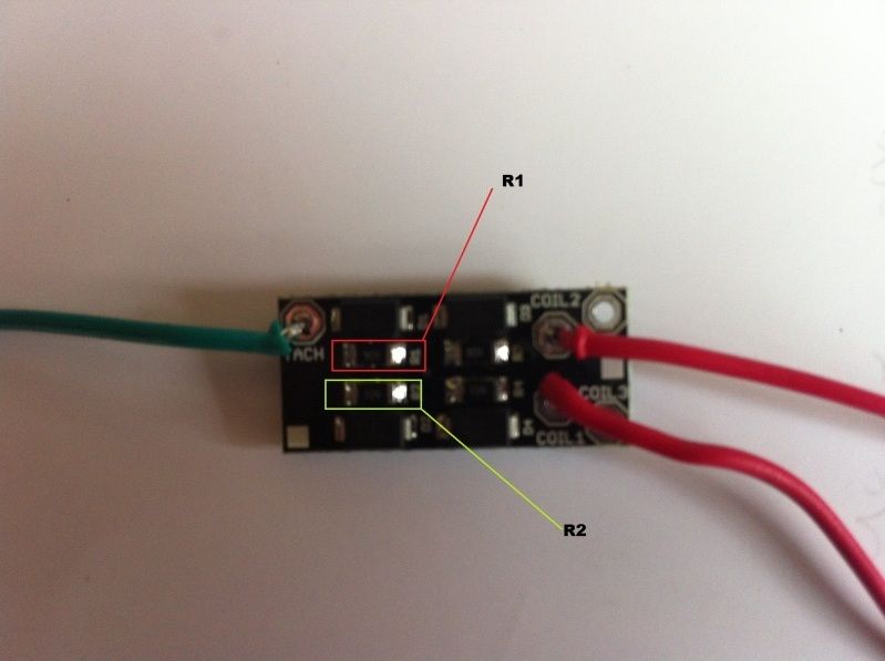
1. If you have coil 1 and 2 pads connected on the adapter board, you can try removing resistors one at a time to see if you get a signal. If you have a fine tip soldering iron you can heat up Resistor R1, remove it, and test it. If that does not work, remove R2. and try again. This will check if the resistors in the circuit are interfering with the operation.
2. Try adding a zener diode between the tach adapter and your rev counter. Use a 15-18 volt zener diode, with the band pointing towards the tach adapter.
3. Contact the tachometer manufacturer and ask for their technical assistance, describing what you are trying to achieve. It should be a relatively common topic for them.
Please keep us posted on your progress!
Tachometers vary quite a bit in what they need for a signal, and can be tough to get right in some cases.
We designed our tach adapter to follow the widely known diode isolation circuit plus the addition of 100K bypass resistors as some tachs seem to need to see a small constant 12v signal between ignition pulses; the older Porsche 914 tach we are using in our race car is one example.. So, it should work with the vast majority of tachometers out there.
Schematics here:
http://www.autosportlabs.net/images/4/4 ... er_sch.png
What you can try doing:
1. If you have coil 1 and 2 pads connected on the adapter board, you can try removing resistors one at a time to see if you get a signal. If you have a fine tip soldering iron you can heat up Resistor R1, remove it, and test it. If that does not work, remove R2. and try again. This will check if the resistors in the circuit are interfering with the operation.
2. Try adding a zener diode between the tach adapter and your rev counter. Use a 15-18 volt zener diode, with the band pointing towards the tach adapter.
3. Contact the tachometer manufacturer and ask for their technical assistance, describing what you are trying to achieve. It should be a relatively common topic for them.
Please keep us posted on your progress!
Yep, those are the resistors. Removing those is what we're suggesting, *as a test*. we don't know the tachometer you're using, so it's what we would actually do to find out how to make it compatible.
If you don't have a soldering iron capable of removing those resistors, you can check around your community to see who might help.
Getting these tachometers working can be tricky- and we'll help as much as we can.
If you don't have a soldering iron capable of removing those resistors, you can check around your community to see who might help.
Getting these tachometers working can be tricky- and we'll help as much as we can.
I did step 1 with no luck, then added a 15 volt zender diode and it worked. zener diode cost me $0.72.brentp wrote: What you can try doing:
1. If you have coil 1 and 2 pads connected on the adapter board, you can try removing resistors one at a time to see if you get a signal. If you have a fine tip soldering iron you can heat up Resistor R1, remove it, and test it. If that does not work, remove R2. and try again. This will check if the resistors in the circuit are interfering with the operation.
2. Try adding a zener diode between the tach adapter and your rev counter. Use a 15-18 volt zener diode, with the band pointing towards the tach adapter.
I agree with mini, for the cost/frustration/convenience factor, it should probably be included in the kit.